
BORACO engineering solution
Multi-Operation Combination Tools
A combination tool is considered when related operations can be integrated into one body without exceeding the component, machine, or process constraints. The tool is engineered from the complete machining sequence, not by simply placing several cutting edges on one body.
Combination versus multi-stage tools↗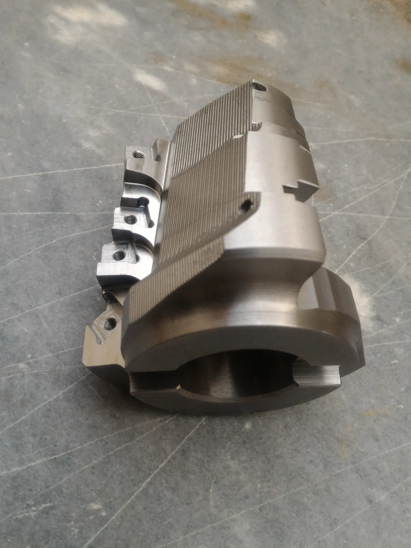
Engineering from the complete operation sequence
The drawing, machine, and process constraints define the feasible combination
Engineering starts with the component drawing, required operations, and operation sequence, together with the machine model, spindle or turret interface, working envelope, available power and spindle speed, setup, workholding, and cutting-zone access. Generic examples include boring with facing and chamfering, drilling with counterboring and chamfering, and turning with grooving; feasibility remains project-specific.
Combination tools may be considered for CNC lathes, CNC milling machines, special-purpose machines, and transfer machines. These categories do not imply compatibility with every machine; the available envelope, machine capability, interface rigidity, operation sequence, and cutting-zone access must be verified for the application.
Tool architecture and cutting-feature distribution
Bodies, pockets, cartridges, and integral features are arranged around the operations
The architecture may use an indexable tool body, independent insert pockets, multiple cartridges, integral cutting features, or a combination of these arrangements. Each operation may use a separate insert, operations may be distributed between pockets or cartridges, or one insert may generate more than one related feature. No arrangement is universal.
Tool-body material is selected according to geometry, loading, required rigidity, application, and operating conditions. BORACO uses appropriate engineering steels and specialized tool steels according to application requirements. Required hardness and heat-treatment specifications are defined as part of the engineering process.
Sequential and simultaneous engagement
Edge engagement follows geometry, load distribution, and process stability
Operations may enter the cut sequentially, multiple operations may engage simultaneously, or a project may use both arrangements. Simultaneous engagement requires review of combined loading, load direction, edge interference, machine and tool rigidity, chip interaction, and process stability; simultaneous machining is not guaranteed for every application.
- 01Review edge count, position, and engagement sequence
- 02Assess load distribution, body section, overhang, and interface rigidity
- 03Check edge interference and actual cutting-zone access
Engineering objectives of a combination tool
Process advantages are treated as conditional design objectives
Where technically suitable, integrating related operations may support fewer tool changes or setups and closer control of dimensional relationships between machined features. Actual results depend on the component, machine, setup, cutting conditions, and production validation. No cycle-time, cost, tool-life, output, or quantified improvement is guaranteed.
- 01Potentially reduce tool changes or setups
- 02Integrate related operations within a feasible architecture
- 03Support repeatability between related features, subject to the process
Insert selection and pocket design
The body and tool components are engineered around inserts that can be sourced
BORACO engineers combination-tool bodies, insert pockets, and cartridges around suitable market-available inserts or special inserts separately sourced and supplied by the customer. Insert availability and suitability for each operation, workpiece material, and machining conditions are verified during the technical review.
- 01Confirm insert suitability for each operation and available space
- 02Review insert-pocket or cartridge position and cutting-edge path
- 03Confirm sourcing before the architecture is finalized
Cutting loads, chip evacuation, and coolant routing
Edge loading and chip and coolant paths are reviewed as one system
Edge count and position, engagement sequence, relative cutting-load direction, body cross-section, overhang, interface rigidity, and pocket or cartridge position are engineering considerations. This review does not guarantee chatter elimination, surface finish, tool life, or cycle time.
Available chip-exit paths, chip-flow direction and interaction, edge spacing, insert position, and engagement sequence are reviewed for the actual process. Where required and technically feasible, separate coolant paths, a shared coolant path, or a combination may be used. Routing follows cutting-zone access, chip evacuation, machine capability, and internal space; universal chip control or internal-coolant feasibility is not guaranteed.
Machine interface, cartridges, and adjustment
The interface and adjustment system follow the machine and tool architecture
Depending on machine and application requirements, interfaces may include BT, SK, HSK, Capto, VDI, an arbor, Weldon, or a cylindrical shank. These are examples rather than an exhaustive list; the final interface must match the spindle or turret, working envelope, loading, and rigidity requirements.
Where required, radial adjustment, axial adjustment, or both may be provided through standard or project-specific cartridges. Not every combination tool is adjustable, and the final arrangement follows the geometry and adjustment requirements of the project.
Final inspection and sample-part evaluation
Inspection is defined for the individual architecture and application
In suitable architectures using an appropriate adjustment or cartridge system, adjustment capability for some relevant characteristics may reach approximately ±0.01 mm. This is not a general or guaranteed tolerance for every tool; achievable results depend on tool architecture, insert and machine condition, setup, rigidity, cutting loads, edge-engagement sequence, cutting conditions, and the measurement and control method.
Relevant dimensional and geometric characteristics are checked according to the tool architecture and intended application. Depending on the design, these may include runout, diameters, axial distance between cutting edges, cutting-edge heights, insert-pocket positions, overall or tool length, angles, and concentricity; the same list does not apply to every tool.
In some projects, the customer may provide a limited number of sample components and the manufactured tool may be evaluated with those samples when the necessary testing conditions are available. In other projects, evaluation is based on relevant dimensional and geometric inspection. Sample machining is not guaranteed for every project, is not serial production of customer components, and does not guarantee production results.
- 01Define checks relevant to the architecture and application
- 02Select an appropriate measurement and control method
- 03Use limited customer samples only when suitable testing conditions are available
Information required for engineering review
A combination tool is engineered from the complete process and machine constraints
The initial review requires the component drawing, workpiece material and hardness, machine model and interface, required operations and sequence, available spindle speed and relevant machine power, tolerances and surface finish, production quantity, current tooling and setup, and the current process problem, together with access, workholding, and chip constraints.
- 01Component drawing and required operations and sequence
- 02Workpiece material and hardness, machine, and spindle or turret interface
- 03Working envelope, relevant speed and power, access, and workholding constraints
- 04Tolerances, surface finish, production quantity, and current tooling and setup
- 05Current process problem and chip-evacuation constraints
Send the drawing, workpiece material and hardness, machine and interface, required operations and sequence, tolerances and surface finish, production quantity, current tooling, and process problem for an engineering review.
Start an engineering review ↗