BORACO

Precision Grooving Toolholder with Replaceable Insert

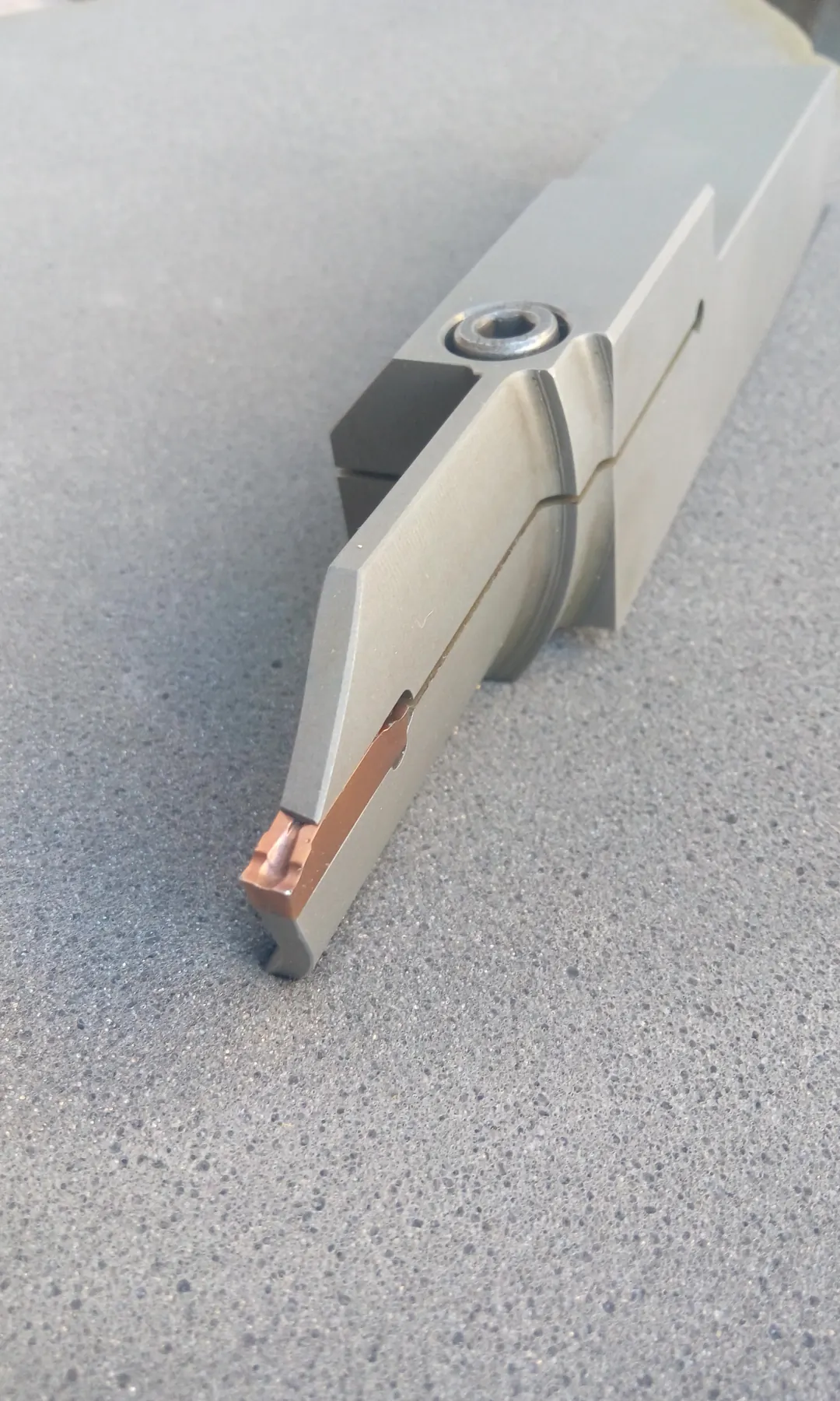
This page presents an actual precision grooving toolholder engineered and manufactured by BORACO. It was developed to reach a specified groove where restricted access and the required cutting-edge position limit the use of a conventional holder. The existing image shows the actual BORACO-manufactured tool.

Chip evacuation under restricted access
Precision grooving toolholder with replaceable insert manufactured by BORACO
01

The cutting edge must reach the specified groove within restricted space

Precision grooving under constrained access requires the tool-body shape and cutting-edge position to be developed around the available space. The engineering objective is to reach the required groove while preserving body clearance and avoiding unwanted interference with the component. The specific groove classification of the pictured tool is not published.

02

An angled or offset body carries one dedicated pocket and one replaceable insert at the tool end

The pictured tool uses an angled or offset body geometry, one dedicated insert pocket, and one replaceable insert positioned at the end of the tool. The body geometry and pocket position were engineered to place the cutting edge at the required location while avoiding interference between the tool body and component. Dimensions, angles, pocket coordinates, the exact edge position, and proprietary project details are not published.

Tool-body material is selected according to geometry, loading, free length, required rigidity, and application. Engineering steels or specialized tool steels may be selected as required by the design, with hardness and heat-treatment specifications defined during engineering.

The connection or interface is selected according to the machine and setup. The actual interface used by the pictured tool is not disclosed.

03

The body and pocket are engineered around a suitable insert and a controlled cutting-edge position

BORACO engineers and manufactures the tool body and insert pocket around a suitable market-available insert or a special insert separately sourced and supplied by the customer. The insert used in the pictured tool is not identified; BORACO’s confirmed manufacturing scope here is limited to the tool body and pocket.

The replaceable-insert architecture allows the tool body to remain in service while the consumable cutting edge is replaced. This is an architectural characteristic, not a quantified saving or a tool-life guarantee.

Cutting-edge position is controlled through the engineered relationship between the tool body, insert pocket, and insert. Exact positioning and setup values are not disclosed, and no adjustment mechanism is claimed for the pictured tool.

04

Free length, body cross-section, and access are reviewed with cutting-edge loading

Engineering review may cover tool-body rigidity, free length, body cross-section, access to the groove, cutting-edge loading, possible body-to-component interference, and machine and setup conditions. These considerations do not guarantee vibration elimination, chatter-free machining, absolute process stability, surface finish, or tool life.

05

The chip-exit path and coolant direction are reviewed around the available cutting space

Relevant considerations include chip-exit path and direction, available groove space, clearance around the cutting edge, and reducing the risk of chip accumulation or recutting. Engineering choices address these risks but do not guarantee complete chip control.

Coolant strategy is reviewed according to the process and may direct coolant toward the cutting zone where required. Internal coolant is not claimed for the pictured tool, and no pressure, flow rate, channel size, or proprietary routing is published.

06

Project-specific dimensional controls are selected from the actual requirements

Tolerances are project-specific and controlled. Relevant inspection categories may include insert-pocket position, cutting-edge height and position, alignment, tool length, and characteristics associated with groove width or position; not every listed inspection applies to every tool.

Dimensional inspection may be performed using relevant measuring equipment. Where conditions permit, a limited number of customer-supplied sample components may be used for evaluation. This does not state that sample machining was performed for the pictured tool.

Accessing a specific groove, maintaining suitable rigidity within restricted space, using a replaceable cutting edge, improving repeatability, and improving chip-management conditions may be engineering objectives. They are not presented as measured achievements, performance guarantees, or confirmed results for the pictured tool.

07

Assessment begins with the component drawing, groove location, and access constraints

The initial review requires the component drawing, groove location and geometry, groove width and depth, workpiece material and hardness, machine and interface, access limitations, tolerance, surface-finish requirement, production quantity, current tool, and the current process problem.