
BORACO engineering solution
Boring and Grooving Tools
Boring and grooving tooling is considered when standard tools cannot provide the required access, rigidity, chip path, dimensional control, or operation arrangement. The tool is engineered from the bore or groove geometry and actual machining process, not from an isolated tool shape.
Guide to high-overhang boring bars↗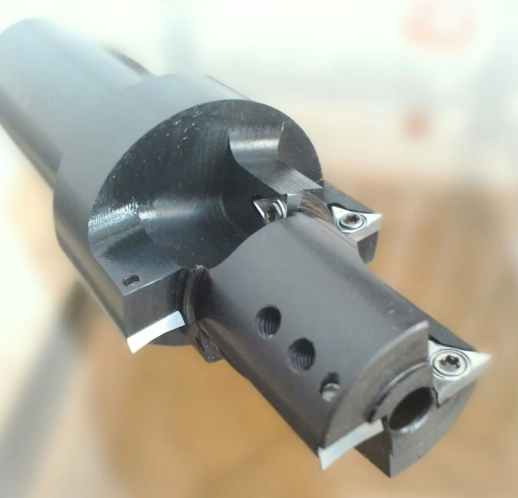
Engineering from the bore, groove, and machine
Component geometry and the actual process define the tool architecture
Subject to technical feasibility and project requirements, a tool may be considered for boring, internal turning, internal or external grooving, facing, chamfering, or a combination of these operations. Component geometry, bore or groove access, machine capability, available envelope, tool diameter, overhang, rigidity, insert availability, chip evacuation, and cutting conditions determine which combination is practical; not every combination is feasible in every tool.
Tool-body material is selected according to geometry, loading, required rigidity, application, and operating conditions. BORACO uses appropriate engineering steels and specialized tool steels according to application requirements. Required hardness and heat-treatment specifications are defined as part of the engineering process.
Machine and setup constraints
Interface, working envelope, and access are reviewed with the cutting geometry
The machine model, interface, working envelope, approach direction, workholding and setup constraints, and effective loading are assessed with the bore diameter and depth or groove dimensions. The result may be a single-edge boring tool, a multi-edge architecture, a precision grooving tool, or a combination boring, facing, and chamfering tool. These are generic examples; the final architecture follows the project data.
Single-edge and multi-edge architectures
Edge count and pocket position follow the operations and cutting-load distribution
BORACO manufactures single-edge boring and grooving tools as well as multi-edge tool architectures. In a multi-edge tool, operations may be distributed between separate insert pockets or cartridges; edge count, pocket position, body rigidity, and cutting-load distribution are reviewed for the specific application.
In appropriate designs, the edge position or cutting-edge height may be adjustable. Adjustability is not a universal feature of multi-edge tooling and is considered only where the project architecture and adjustment system support it.
- 01A single-edge boring or grooving tool for a defined operation
- 02A multi-edge architecture with separate insert pockets or cartridges
- 03Rigidity, edge count, and load-distribution review without a guaranteed performance claim
Long-overhang boring applications
Feasibility is assessed from free length, tool diameter, and the actual machining conditions
BORACO engineers boring tools for applications requiring substantial free length or a high length-to-diameter relationship. The actual bore, tool diameter, free length, machine, interface, setup rigidity, and cutting conditions must be reviewed together; not every long-overhang application is feasible.
Body section and rigidity, cutting-load direction and relative magnitude, edge count, and insert-pocket position are design considerations. This review does not imply elimination of chatter or guaranteed surface finish, tool life, or cycle time.
- 01Review the bore geometry and tool approach path
- 02Assess diameter, free length, interface, and machine and setup rigidity
- 03Select an architecture for the cutting conditions and available envelope
Insert selection and pocket design
The tool is engineered around an insert that can be sourced for the project
BORACO engineers the tool body, insert pockets, and cartridges around suitable market-available inserts or special inserts separately sourced and supplied by the customer. Insert availability and suitability for the operation, workpiece material, and machining conditions are verified during the technical review of each project.
- 01Match insert geometry to the boring or grooving operation
- 02Review access, chip space, and insert-pocket or cartridge position
- 03Confirm insert sourcing before the tool architecture is finalized
Chip evacuation and internal coolant
Chip paths and coolant access are treated as part of the tool architecture
Tool and pocket geometry, the available chip-exit path, chip-flow direction, and insert position are reviewed for the bore or groove. Where requested by the customer and technically suitable, internal coolant channels may be incorporated and directed for cutting-zone access and chip-evacuation requirements; chip control is not guaranteed for every condition.
Machine interface, cartridges, and adjustment
The interface and adjustment system follow the machine and tool architecture
Depending on machine and application requirements, interfaces may include a cylindrical shank, Weldon, BT, SK, HSK, Capto, VDI, or an arbor. These are examples rather than an exhaustive list; the final interface must suit the machine, turret or spindle, available space, and loading conditions.
Where required by the application, radial adjustment, axial adjustment, or both may be provided through a suitable cartridge system. A project-specific cartridge may be designed and manufactured where standard cartridge geometry or adjustment range is insufficient. Cartridges and adjustability are not assumed for every boring or grooving tool.
Final inspection and sample-part evaluation
Adjustment capability and evaluation are defined for the individual architecture and application
In suitable tool architectures using an appropriate adjustment or cartridge system, adjustment capability for some relevant characteristics may reach approximately ±0.01 mm. This is not a general or guaranteed tolerance for every tool; achievable results depend on tool architecture, insert and machine condition, setup, rigidity, overhang, cutting conditions, and the measurement and control method.
Relevant dimensional and geometric characteristics are checked according to the tool design and intended application. Depending on the architecture, these may include runout, diameter, cutting-edge height, insert-pocket position, concentricity, overall or tool length, and groove width; the same list does not apply to every tool.
In some projects, the customer may provide a limited number of sample components and the manufactured tool may be evaluated with those samples when the necessary testing conditions are available. In other projects, evaluation is based on relevant dimensional and geometric inspection. Sample machining is not guaranteed for every project, is not serial production of customer components, and does not guarantee production results.
- 01Define dimensional and geometric characteristics relevant to the specific tool
- 02Select an inspection method suited to the architecture and application
- 03Use limited customer samples only when suitable testing conditions are available
Information required for engineering review
The tool is engineered from the bore or groove geometry and actual machining process
The initial review considers the component drawing and bore or groove data together with the machine, interface, cutting conditions, and current process problem. Complete inputs support a realistic assessment of access, rigidity, single-edge or multi-edge architecture, chip evacuation, interface, adjustment, and inspection method.
- 01Component drawing, bore diameter and depth, and groove width and depth
- 02Workpiece material and hardness, machine model, and machine interface
- 03Required tolerances, required surface finish, and available working space
- 04Production quantity, current tool or process, and current machining problem
- 05Relevant access, setup, workholding, and other process constraints
Send the drawing, bore or groove geometry, workpiece material and hardness, machine and interface, tolerances and surface finish, production quantity, and current process problem for an engineering review.
Start an engineering review ↗