BORACO

Multi-Edge Boring Tool

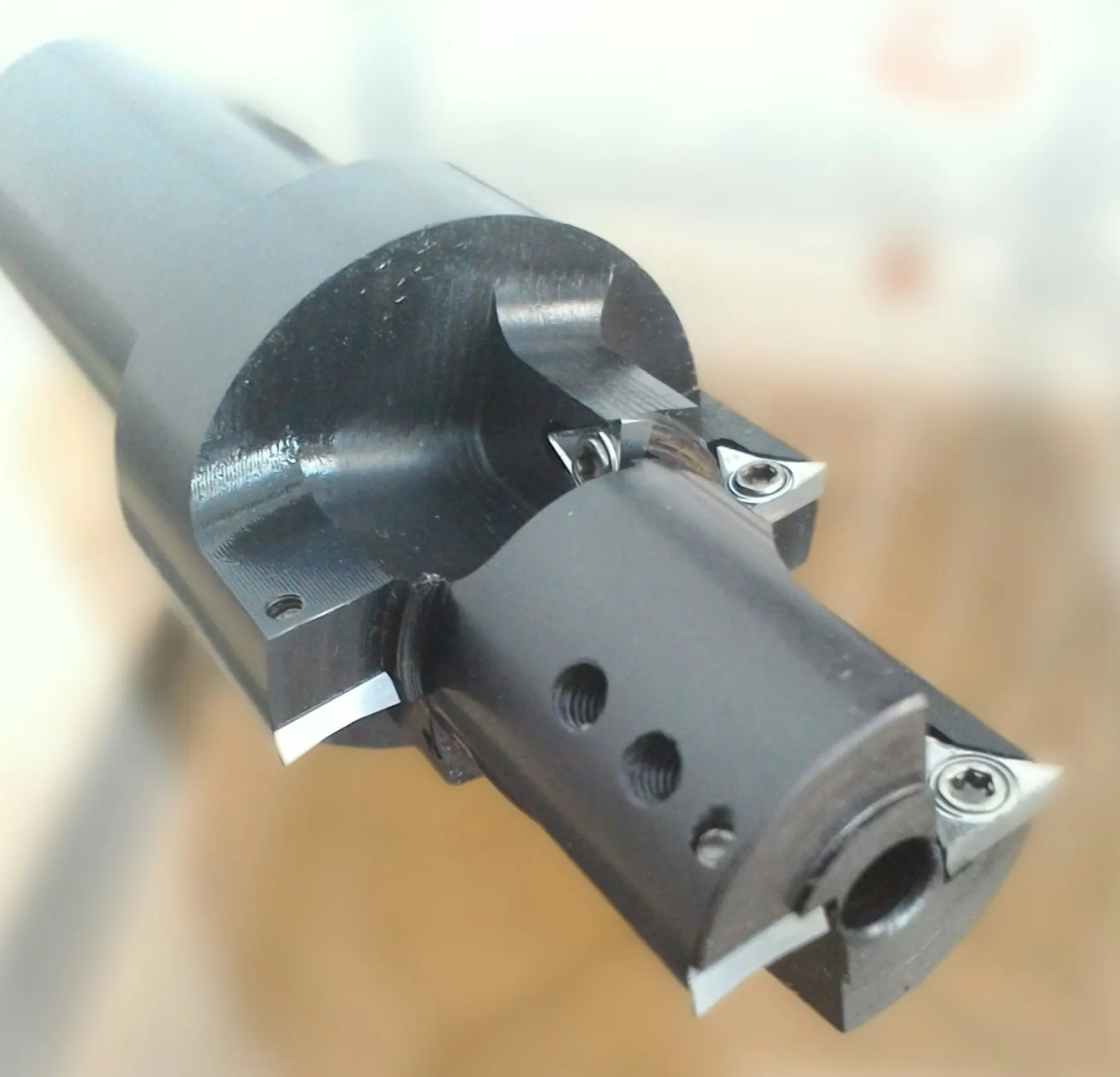
This page presents one real BORACO project: a multi-edge boring tool engineered and manufactured for a customer-specific industrial machining application. The existing image shows the actual tool manufactured for this project.

Edge-height control in multi-edge tools
Multi-edge boring tool manufactured by BORACO
01

The existing process relied on separate tools and did not provide the required stability

Excessive machining time, multiple separate tools, insufficient dimensional repeatability, runout-related concerns, vibration-related process instability, and inadequate tool life were among the initial project drivers. They were treated as engineering challenges and validation criteria; no numerical result or final project performance is published.

02

The cutting-edge and pocket arrangement followed the component drawing and actual process

The multi-edge architecture was defined from the customer component drawing, required machining process, geometry and access, body rigidity, cutting-load distribution, insert-pocket positions, and machine and setup constraints. The edge count and detailed geometry are project-specific and are not published; this arrangement is not presented as a standard architecture for every BORACO multi-edge tool.

Tool-body material and required hardness were selected according to tool geometry, loading, required rigidity, and the intended application. Appropriate engineering steels or specialized tool steels may be selected as required by the design.

03

Insert sourcing and the adjustment strategy were aligned with the project architecture

BORACO engineers tool bodies and insert pockets around suitable market-available inserts or special inserts separately sourced and supplied by the customer. Insert availability and suitability for the operation and machining conditions are verified during technical review; the exact insert used in this project is not identified.

Cutting-edge position and the required adjustment strategy were defined according to the project architecture, with radial, axial, or combined adjustment available where technically required. The mechanism, cartridge geometry, adjustment range, and setup procedure for this tool are not published.

04

Body section, loading, and chip-clearance paths were reviewed with the machine constraints

Body rigidity, free length, tool diameter, cutting-edge count, insert-pocket position, cutting-load distribution, and machine and setup conditions were engineering considerations. This review does not imply chatter elimination, vibration-free machining, guaranteed surface finish, or guaranteed tool life.

Clearance or chip-relief provisions, available chip-exit paths, chip-flow direction, and insert-pocket position are reviewed for the project geometry. Internal coolant may be incorporated where required by the process and supported by the architecture, but its presence in this specific tool is not confirmed or claimed.

The machine interface and available working envelope were incorporated into the project design without publishing the machine model or interface type.

05

Project-specific tolerances and relevant inspection categories were defined without publishing customer values

Applicable dimensional and geometric tolerances were defined and controlled for the project without publishing customer-specific values. Relevant inspection categories may include diameter, runout, cutting-edge height, insert-pocket position, concentricity, tool length, and other characteristics required by the architecture; this does not state that every listed check applies to every tool.

06

The design review focused on integrating the required functions while controlling process stability

The engineering review focused on consolidating the required cutting functions while controlling rigidity, cutting-edge position, runout-related characteristics, and process stability. Project performance was evaluated against the customer’s internal production criteria, but the evaluation outcome and performance results are not published.

For similar projects, evaluation may be based on dimensional and geometric inspection and, where conditions permit, a limited number of customer-supplied sample components. This is a general process statement and does not claim that sample machining was performed for this project.

07

Assessment begins with the component drawing and actual machining constraints

The initial review requires the component drawing, bore geometry, workpiece material and hardness, machine and interface, required operations, tolerance and surface-finish requirements, current tooling, and the current process problem.