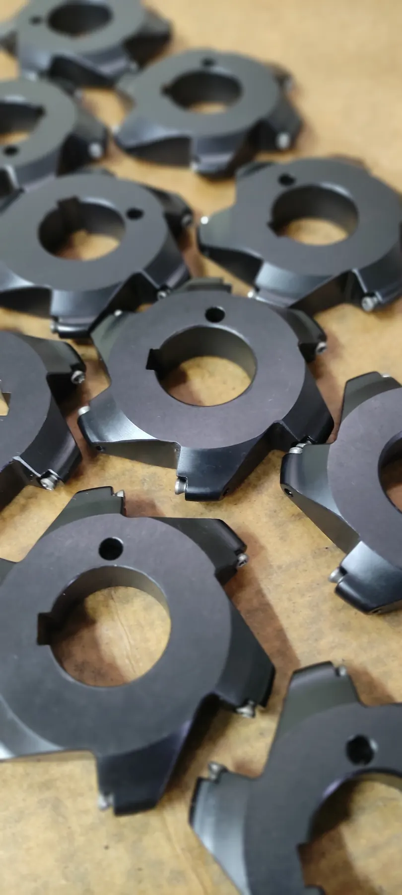
Real disc form cutter example · FORM / 02
Disc Form Cutters
This page presents real disc form cutters engineered and manufactured by BORACO. These indexable tools are developed to generate a defined form or profile with replaceable cutting edges. The existing image shows actual tools manufactured by BORACO.
Splitting a profile between multiple inserts↗
Engineering challenge
The required form must be generated with replaceable edges and a process-specific architecture
Engineering objectives include repeatable generation of the required profile, control of the resulting form, and replaceable cutting edges so that wear does not require replacement or regrinding of the complete tool body. Each architecture must be adapted to the actual component, machine, setup, and process constraints; these objectives are not guaranteed project outcomes.
Confirmed tool architecture
The indexable disc body uses independent pockets with matching geometry
The tool shown uses an indexable disc body with multiple independent insert pockets. All pockets share the same geometry and are uniformly positioned on the body. The exact pocket and cutting-edge count and detailed project geometry are not published.
Tool-body material is selected according to geometry, loading, required rigidity, and application. Engineering steels or specialized tool steels may be selected as required by the design, with hardness and heat-treatment specifications defined during engineering.
The connection is selected according to the machine and tool architecture and may use an Arbor or another technically suitable interface.
Profile and insert strategy
Profile distribution and insert selection follow the geometry and real process constraints
In complex form tools, the profile may be distributed across multiple inserts or pockets. The engineering decision depends on the required profile geometry, manufacturability, cutting-edge engagement sequence, cutting-load distribution, chip path, and machine and setup limitations. In some architectures, one insert may generate more than one related part of a profile; this is not presented as a feature of every disc cutter or as a confirmed detail of the pictured tool.
BORACO engineers the tool body and pockets around suitable market-available inserts or special inserts separately sourced and supplied by the customer. Insert availability and suitability for the profile and machining conditions are verified during technical review.
Radial, axial, or combined adjustment may be designed where technically necessary and supported by the architecture. An adjustment mechanism is not claimed for the pictured tool.
Rigidity, chip flow, and coolant
Body rigidity, edge engagement, and pocket clearance are reviewed with the chip path
Engineering review may cover body rigidity, chip-exit path and direction, clearance around the pockets, distance between cutting edges, engagement sequence, and cutting-load distribution. The design choices depend on the tool geometry, process, and machine constraints and do not constitute a guaranteed performance result.
Coolant strategy is reviewed according to the process. Internal or directed coolant may be incorporated only where required and supported by the architecture; internal coolant is not claimed for the pictured tool.
Tolerance and dimensional control
Project-specific tolerances determine the relevant inspection categories
Tolerances are project-specific and controlled through engineering and inspection. Relevant categories may include runout, pocket position, cutting-edge height, concentricity, profile width or position, and other characteristics required by the architecture; not every listed inspection applies to every tool.
Validation and engineering objectives
Evaluation relies on geometric inspection and the actual conditions of use
Dimensional and geometric inspection may be performed using relevant measuring equipment. Where conditions permit, a limited number of customer-supplied sample components may be used for evaluation. This does not state that sample machining was performed for the pictured tool.
For similar projects, reducing separate tools or process stages, improving profile repeatability, enabling economical maintenance through insert replacement, and adapting the process for series-production requirements may be engineering objectives. They are not presented as measured achievements or performance guarantees.
Information required for a similar review
Assessment begins with the component drawing and the required profile
The initial review requires the component drawing, required profile, material and hardness, machine and interface, tolerances, surface-finish requirements, production quantity, current tool or method, and the current process problem.