
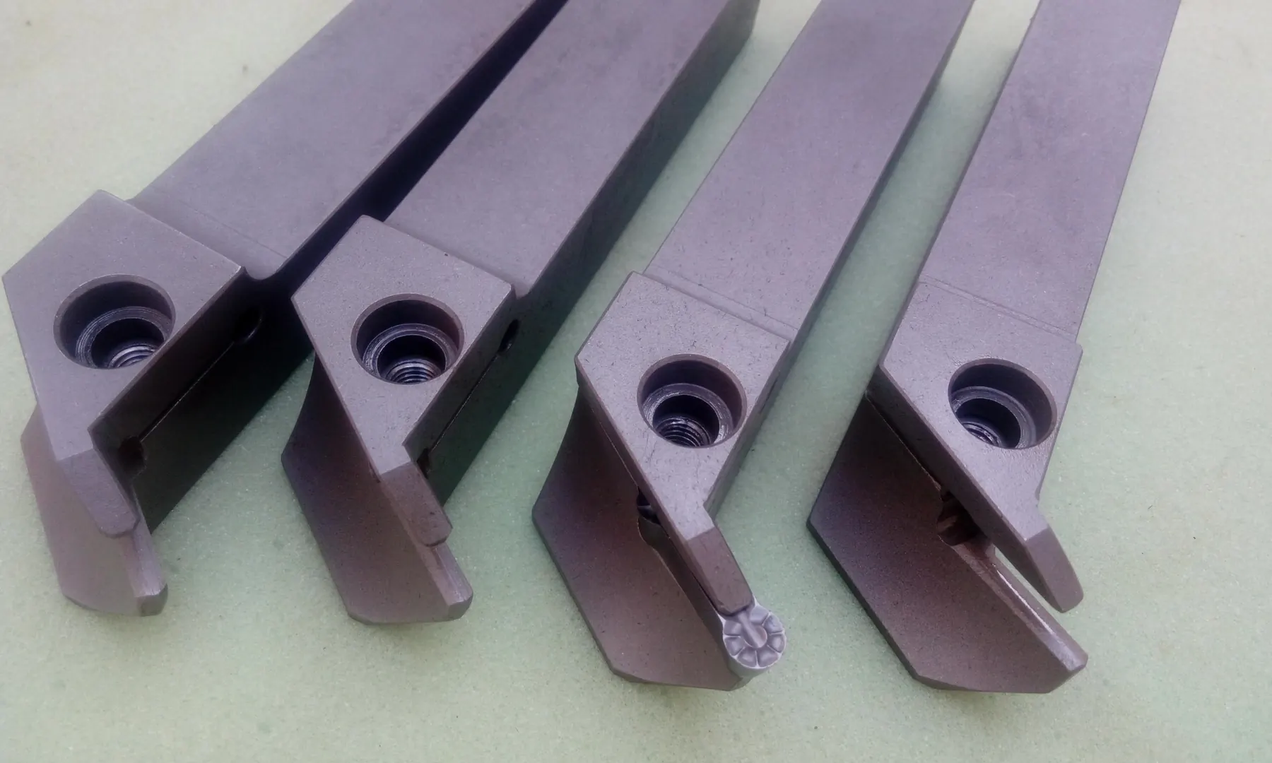
The problem and why it matters
A trapped chip can be recut, damage the finished surface or apply a sudden load to the edge during internal grooving.
Chipbreaker direction, body clearance, entry and withdrawal sequence and coolant delivery need to be designed as one system.
Selection and design logic
Trials should record chip form, exit path and evidence of recutting. Higher coolant pressure alone is not a solution when no exit path exists.
The designer must estimate chip volume per revolution, natural flow direction and the clearance between body and bore. A structurally strong body can still block the exit channel and compress chips against the newly machined surface.
Implementation details and controllable errors
Chipbreaker geometry must suit the material and feed range so that transportable chips are produced. An internal or directed nozzle should guide chips toward the exit rather than drive them into the groove end. Tool entry and withdrawal are also part of process design.
Evaluation and conclusion
During trials, record chip shape and length, edge temperature, surface scratching and chip accumulation after each pass. If chips form correctly but cannot leave, revise the channel and coolant direction; if chips are long, review edge geometry and cutting data first.