
The problem and why it matters
There is no universal tolerance for every pocket. Requirements derive from insert geometry and class, clamping method, workpiece dimensions and the allowable share of total error.
Edge position is the result of body, pocket, insert, screw, holder and spindle errors. Controlling one surface alone is not sufficient.
Selection and design logic
The insert maker’s drawing, functional datums and a repeatable inspection method should define the manufacturing drawing and final control plan.
Allocate pocket tolerance backward from the permissible cutting-edge error. Assigning the entire tip-position allowance to one pocket dimension ignores insert, assembly, holder and measurement variation and makes the real result unpredictable.
Implementation details and controllable errors
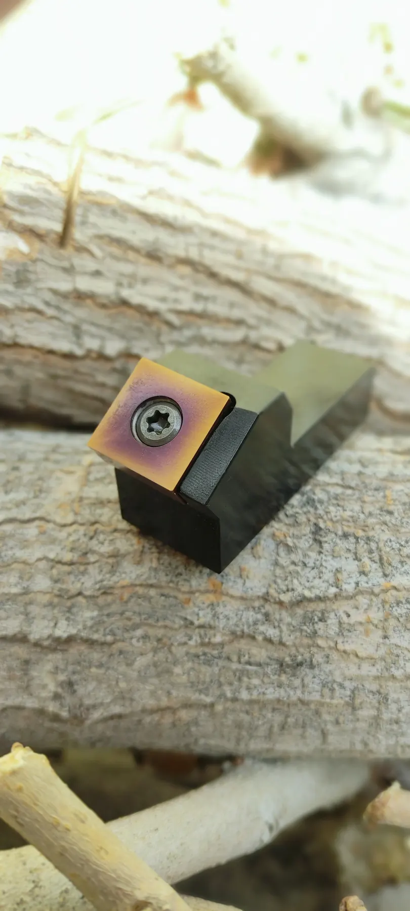
The pocket floor influences insert height and angle; reference walls locate it laterally and resist cutting force. Flatness, perpendicularity, thread position and corner relief must match the insert and clamping mechanism.
Evaluation and conclusion
A sound inspection plan combines direct measurement of pocket features with a functional check using a reference insert or master. Repeated assembly and measurement reveal repeatability and show whether a tight geometric tolerance is necessary or assembly practice is driving variation.