
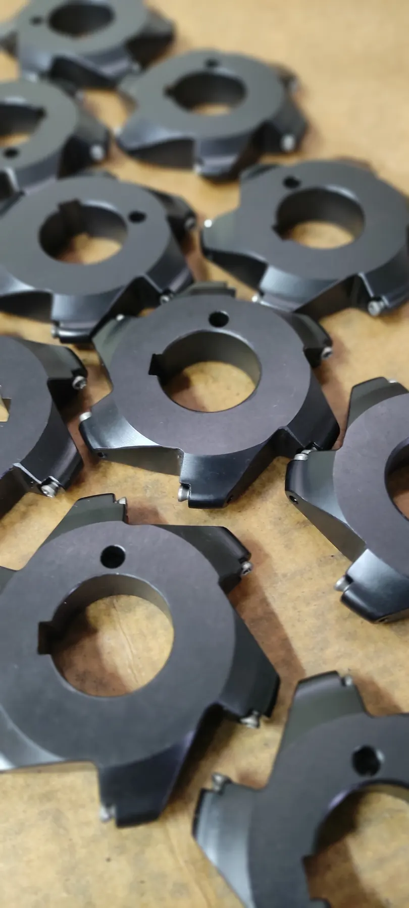
The problem and why it matters
Profile splitting is useful when contact length, cutting force or insert-manufacturing limits prevent the complete form from being assigned to one edge.
Overlap must avoid a step, witness line or sudden load change, while assembly errors are included in the tolerance chain.
Selection and design logic
Edge engagement sequence, chip space and the ability to inspect each stage independently determine the final tool architecture.
Divide the profile into roughing, semi-finishing and finishing zones. The finishing edge should not have to correct excessive error from a preceding edge, and the split is best placed in a less surface-sensitive or lower-curvature region.
Implementation details and controllable errors
Geometric overlap prevents an uncut step, but excessive overlap raises contact and force. Radial and axial insert positions, pocket-manufacturing tolerances and insert variation should all be evaluated in a worst-case stack.
Evaluation and conclusion
Inspect each stage independently and then verify the complete assembly. On the machined part, use a profilometer or suitable metrology to confirm that the transition is not detectable in dimension or surface quality.